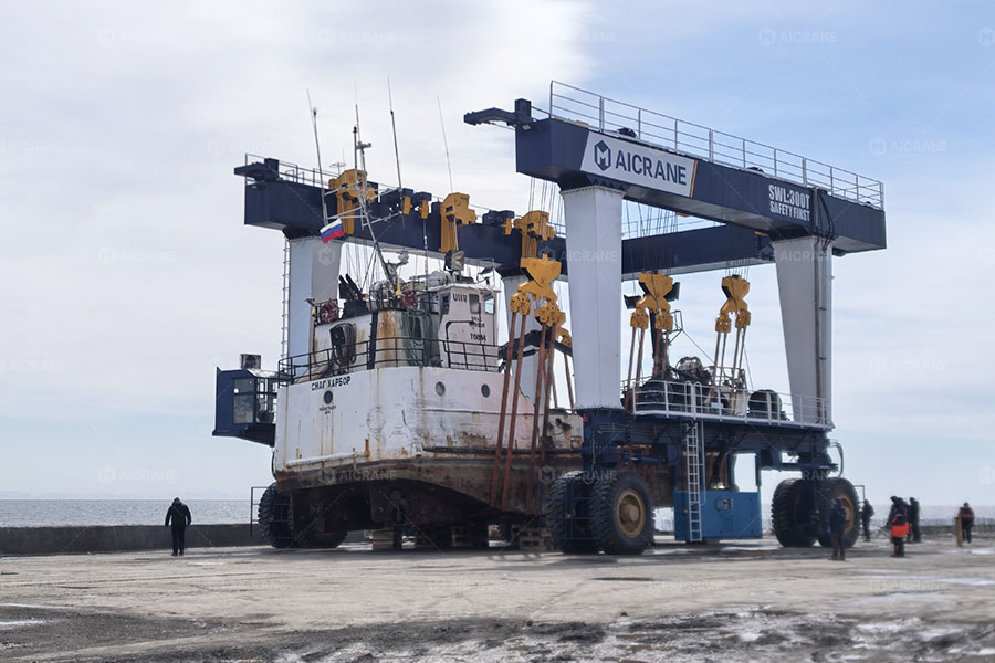
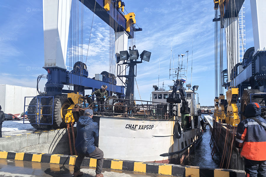
n commercial shipyards, recreational yacht marinas, and busy boat basins, a marine travel lift – also commonly referred to as a mobile boat hoist, boat travel lift, or marine straddle carrier—is a critical piece of industrial equipment for vessel transport and haul-out operations. Whether managing a standard 50-ton hoist for recreational center-consoles or operating a heavy-duty 500-ton vessel gantry crane for commercial trawlers, a sudden failure in the hoisting function immediately halts yard operations.
A hoisting failure during peak seasonal haul-outs or emergency repair scheduling leads to immediate operational bottlenecks and significant financial liabilities. For shipyard managers, marine operators, and hoist technicians, implementing a structured, logical diagnostic process is essential to resolve this issue safely and restore yard productivity.
This guide outlines a professional, step-by-step diagnostic framework to isolate and resolve the root causes of a hoisting failure across various marine travel lift models and capacities.
Safety Warning and Protocols
Before performing any physical inspection, electrical testing, or hydraulic troubleshooting on a yacht lifter or mobile boat hoist, you must strictly adhere to the following safety protocols:
- Do not perform diagnostic or repair work under a suspended load. If a vessel is partially lifted in the haul-out slip, safely lower it back into the water or support it with keel stands and structural blocks to release all tension and hydraulic system pressure.
- Implement Lockout/Tagout (LOTO) procedures. Disconnect and lock out the main power source before opening electrical enclosures or working near mechanical drive components, winches, or cable sheaves.
- Wear appropriate Personal Protective Equipment (PPE). High-capacity hydraulic systems operate under extreme pressure. High-pressure oil leaks can penetrate the skin, causing severe internal injuries. Always wear safety glasses and heavy-duty, fluid-resistant gloves during pressure testing.
Phase 1: Preliminary Inspections
Before performing advanced diagnostics, tracing complex PLC electrical circuits, or disconnecting hydraulic hoses, conduct these preliminary checks. These actions exclude the most common and easily accessible causes of hoist failures in marina environments.
1. Emergency Stop (E-Stop) Verification
A frequent cause of sudden equipment shutdown in active shipyards is the accidental activation of an Emergency Stop button by yard personnel or ground spotters. Modern boat travel lifts feature multiple E-stop buttons located on the operator’s cabin console, the wireless transmitter, and at various ground-level points around the structural steel frame.
- Diagnostic Action: Inspect every E-stop button on the machine. Twist and pull each button to ensure they are fully reset to the operational position.
2. Over-Hoist Limit Switch Inspection
To prevent structural damage to the winch drum, structural beam, or wire ropes, marine straddle carriers are equipped with upper limit switches (typically microswitches or weighted cable switches near the top of the hoist frame). In coastal boat basins, salt spray, corrosion, ice, or physical debris can easily jam one of these switches in the “tripped” position, causing the control system to cut power to the hoisting function.
- Diagnostic Action: Visually inspect the limit switch mechanisms at the top of the hoist. Manually actuate them to verify the internal springs return to the default position and that no salt crust or physical blockages exist.
3. Wireless Transmitter and Receiver Communication
When operating a mobile boat hoist via wireless remote control in a crowded marina, signal interference, a low battery, or a failed pairing relay can prevent signal transmission.
- Diagnostic Action: Switch the system from wireless mode to the manual backup controls or the tethered pendant. If the machine operates successfully using manual hydraulic control valves or the hardwired backup, the issue is isolated to the wireless remote subsystem (such as a depleted battery, a blown fuse in the receiver, or lost transmitter pairing).
Phase 2: Hydraulic System Diagnostics
Whether operating a 75-ton yacht hoist or a 300-ton commercial marine travel lift, these machines rely on high-capacity hydraulic closed-loop or open-loop systems. If the preliminary checks do not resolve the issue, the malfunction is likely located within the hydraulic circuit.
1. Hydraulic Fluid Level and Temperature Analysis
- Low Hydraulic Fluid: Causes pump cavitation, introducing air into the system and preventing the hydraulic pump from building the volumetric pressure required to lift heavy vessels.
- Overheated Hydraulic Oil: Operating above 70°C (160°F) reduces fluid viscosity, leading to internal bypassing (slippage) inside the pumps, control valves, and motors, which decreases overall lifting capacity.
- Diagnostic Action: Inspect the oil level sight glass on the reservoir. If the oil appears milky or frothy, water contamination has occurred (a common issue in humid marine environments), and the fluid must be flushed and replaced. Check the temperature gauge; if the system exceeds normal operating limits, shut down the engine and allow the system to cool completely.
2. System Pressure Testing
This is the primary diagnostic step for hydraulic troubleshooting. Connect a calibrated pressure gauge to the dedicated test port on the main hoisting control valve manifold. Actuate the hoist-up command and monitor the pressure readings:
- Zero or Low Pressure: Indicates that the hydraulic pump is not compensating, or the Main Relief Valve is stuck in the open position. If debris or marine grit prevents the relief valve from closing, hydraulic flow routes directly back to the reservoir instead of building the pressure needed to lift the load.
- Maximum Operating Pressure Reached (e.g., 250–280 bar / 3600–4000 PSI) without Movement: Indicates that the hydraulic pump and relief valves are functioning correctly. The issue is likely caused by a structural overload (trying to lift a vessel exceeding the hoist’s rated capacity, such as attempting to lift a 120-ton vessel with a 100 ton travel lift), a locked mechanical brake, or mechanical binding.
3. Control Valve and Solenoid Inspection
The lifting motion is directed by proportional electromagnetic solenoids on the main hoist valve bank. If a solenoid coil fails or a valve spool is physically jammed with varnish or metallic debris, hydraulic oil cannot reach the hoist motors.
- Diagnostic Action:
- Hold a metallic tool (such as a screwdriver) close to the solenoid coil while an assistant triggers the hoist command. If you detect a magnetic pull, the coil is receiving electrical power from the console.
- Locate the manual override pin on the end of the solenoid valve. Depress it using a small hex wrench. If the hoist begins to lift, the issue is within the electrical control circuit (wiring, switch, or failed coil). If manually depressing the pin produces no movement, the valve spool is physically seized, or the hydraulic motor itself has failed.
Phase 3: Electrical and Control System Inspection
If the solenoid valve is not receiving the electrical signal to open, trace the control circuit backward through the electrical cabinet.
1. Fuses, Relays, and Terminal Connections
High-vibration environments in shipyards combined with corrosive marine salt air can cause loose connections, corroded terminal strips, or blown fuses.
- Diagnostic Action: Open the main electrical control box. Inspect all fuses and circuit breakers associated with the hoist logic. Inspect relays for burnt contacts or discoloration, and ensure all wiring terminal screws are tight and free of green copper-carbonate corrosion.
2. Load Moment Indicator (LMI) Calibration and Faults
Modern marine travel lifts utilize electronic load cells integrated into the structural equalizer sheaves to measure vessel weight and prevent dangerous overloads. If a load cell is damaged by physical impact, moisture ingress, or calibration drift, it may transmit an erroneous overload signal to the Programmable Logic Controller (PLC), which automatically disables the hoisting function as a safety precaution.
- Diagnostic Action: Inspect the operator display console. If the load indicator displays a weight reading when the slings are empty, or if the overload warning light is active, the system is in safety lockout. Reboot the control system or consult the technical manual to temporarily place the unit in bypass mode for diagnostic purposes only.
Phase 4: Mechanical and Drivetrain Diagnostics
If electrical signals are active and hydraulic pressure is within operational specifications but the hoisting winch drum does not rotate, the issue is mechanical.
1. Hoisting Brake Release Verification
Marine travel lifts utilize normally closed, spring-applied, hydraulically released multi-disc wet brakes on the hoist gearboxes. These brakes remain locked by heavy springs until hydraulic pilot pressure overrides the internal spring tension during a active lift command.
- The Failure Point: If the brake release line is restricted or the brake piston seals are compromised, the brake will remain engaged, preventing the winch drum from rotating even under full hydraulic motor torque.
- Diagnostic Action: Connect a pressure gauge to the brake release line. Actuate the hoist command and verify that pilot pressure reaches the brake assembly. Listen for the physical release sound from the gearbox. If pressure is present but the drum remains locked, the brake discs may be fused together or mechanically seized due to moisture intrusion.
2. Cable Alignment and Sheave Inspection
- The Failure Point: A wire rope can jump out of its sheave (pulley) groove, wedging itself between the sheave and the side plates. Alternatively, improper spooling or overlapping on the winch drum can physically bind the drum assembly, especially when lifting wide-beam catamarans or deep-draft vessels that require extreme sling angles.
- Diagnostic Action: Conduct a complete visual inspection of the wire ropes along the entire length of the structural frame. Ensure they are seated correctly in every sheave groove and wrapped evenly across the winch drums. Verify that the sheave bearings rotate freely and are not seized.
Troubleshooting Decision Logic
Use this structured logic sequence to systematically identify a hoist failure:
- Verify Electrical Control Status: If the machine does not respond when the lift command is actuated, inspect the E-stops, upper limit switches, and remote control receiver fuses.
- Observe Hydraulic System Behavior: If the engine experiences load but no movement occurs, connect a pressure gauge.
- Address Low Pressure: If pressure is below specifications, inspect the hydraulic oil levels, check for foaming, and clean or replace the main relief valve.
- Address Target Pressure: If target pressure is achieved but no movement occurs, verify that the vessel does not exceed the rated capacity of the lift (e.g., check the vessel’s displacement against the lift’s 50-ton, 100-ton, or 200-ton rating). If the load is within limits, check the brake release line pressure to ensure the mechanical brakes are disengaging.
- Address Defective Solenoids: Depress the manual override pin on the valve bank to bypass the electrical system. If manual override functions, inspect the hoist relays, wiring harness, and load cell calibration.
Preventative Maintenance Practices
- Weekly Safety Procedures: Manually actuate every E-stop and trip the upper limit switches before beginning shipyard operations to ensure responsiveness and prevent corrosion buildup.
- Annual Hydraulic Fluid Analysis: Saltwater and high humidity degrade hydraulic components. Analyze the oil annually to detect water contamination or metallic wear particles before they cause control valve seizure.
- Environmental Protection for Electrical Enclosures: Maintain the seals on all electrical control boxes. Place industrial-grade silica gel packets inside the cabinet to absorb humidity, and regularly apply electronic corrosion inhibitors to terminal blocks to prevent contact failure in wet marina environments.